
When a radar level transmitter shows jumping values, gets stuck or gives a reading when the tank is empty, the first reaction on site is often that the instrument itself has failed. However, in a large number of cases, the root cause actually lies in the installation location—especially when the antenna is too close to the tank wall. The reason wall-adjacent installation is explicitly not advised by manufacturers is not conservatism, but is determined by the physical nature of radar measurement and related to factors such as the radar beam angle, tank wall reflections and internal tank structures.
When a radar level transmitter is operating, the probe antenna emits electromagnetic waves toward the medium surface. When the electromagnetic waves hit the medium surface, they are reflected back and the instrument then calculates the liquid level distance based on the echo time. The emitted radar waves have a certain beam angle.The beam radius can be calculated as follows:
r = H × tan(θ/2)
Where r is beam radius, liquid surface is H and the beam angle is θ. As can be seen, the farther the radar wave travels from the antenna, the larger the coverage area. For the same radar installed on a 3 m tank and a 30 m tank, the difference in beam coverage at low liquid levels will be very obvious. Therefore, when selecting an installation location, attention should be paid to the entire beam path from the antenna probe down to the low-level area.
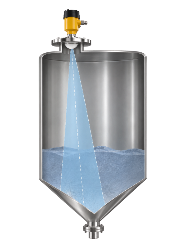
During propagation in the tank, if the radar is too close to the tank wall, part of the beam will illuminate the tank wall, and reflections from a metal tank wall are particularly pronounced. As a result, the echoes received by the instrument will include not only the normal liquid surface but also signals refracted by the wall. At this point, several peaks can be seen in the echo curve. If the liquid surface is stable and the medium reflection is relatively strong, the instrument can identify the measurement relatively easily. However, if the medium has a low dielectric constant or there is foam, steam, agitation, or surface rippling on site, the liquid-surface echo may weaken or disappear, making it more difficult to distinguish false echoes.
In addition to the tank wall, several on-site factors can affect radar echoes.
Feed inlet: the liquid may splash, foam and become turbulent near feed inlet. Solid materials may also form a material stream. Once these disturbances enter the radar beam, the echo will change accordingly. If the installation location is offset from the feed area, the reading can be more stable.
Agitator: If agitator blades are constantly rotating near the radar beam, the reflection position will also change accordingly, causing periodic variations to often appear on the echo curve.
Ladders, coils, and reinforcing structures: Most of these structures are metal components and produce relatively strong reflected signals. When selecting an installation position, the main beam should be kept in an open area as much as possible.
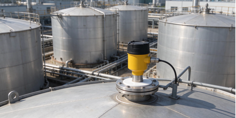
The cleaner the area through which the radar main beam passes, the clearer the echo and the more stable the level measurement. The appropriate distance between the radar and the tank wall needs to be determined based on both the device and the tank itself.
Beam angle: The larger the beam angle, the wider the signal spreads as it propagates downward. For the same measurement distance, a larger beam angle requires a wider space.
Tank height: The taller the tank, the longer the measurement distance at low level, and the beam coverage will increase. Therefore, when selecting an installation location for a tall tank, extra attention should be paid to the low-level area.
Radar frequency and antenna type: Radar level transmitters with different structures differ greatly in beam width. When on-site space is confined, narrow-beam devices are easier to arrange.
Internal tank structures: Metal structures such as ladders, agitator shafts, heating coils, feed pipes, and stiffeners will all produce strong interfering echoes. These factors must be taken into account when selecting an installation point.
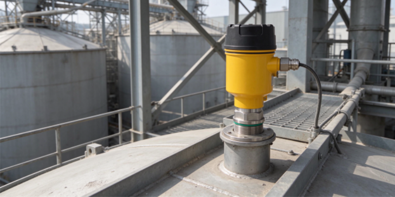
When installing a radar level transmitter, care should be taken to leave a relatively clean propagation path for the radar beam. If the transmitter is too close to the tank wall, the metal structures mentioned above are likely to enter the beam range. The more echoes there are, the more difficult it becomes for the instrument to identify the liquid surface. When selecting a location on site, first consider the downward path of the beam, what interfering factors are nearby and how wide the beam will spread when it reaches the bottom. Once these points are clearly understood, the installation point will basically be determined. As a professional manufacturer focusing on the instrumentation field, Shanghai Wangyuan has more than 20 years of industry experience. If you have any requirements or questions regarding the selection of non-contact radar level transmitters, please feel free to contact us to obtain the most suitable measurement solution.
Post time: Nov-17-2026